






Technical files
Documents
Specifications and installation information can be viewed or downloaded as PDFs from our server.
User manuals
2Key technical specifications
The most critical technical parameters of this product.
- Input voltage 220 VAC 50/60 Hz (±10%)
- Max. current 15 A
- Output power 2200 VA
- Safety photocell voltage 12 – 24 VAC/DC
- Operating temperature -20 – +45 °C
- Motor power options 0.75 / 1.1 / 1.5 / 2.2 kW
Show all technical specifications (13)
Control
| Feature | Value |
|---|---|
| Control DIP switches | 5 switches |
| Motor type DIP switches | 2 switches |
| Number of trimpots | 5 |
| Limit switch inputs | 4 (Sw1-Sw4: opening + closing + deceleration) |
| Encoder support | 5 V/12 V, B, A, GND (encoder terminals) |
| Automatic closing time | T5 trimpot |
| Remote control | Optional external RF-433 receiver |
Videos
You can find all of our product and installation videos on our YouTube channel.
Visit Our YouTube ChannelOverview
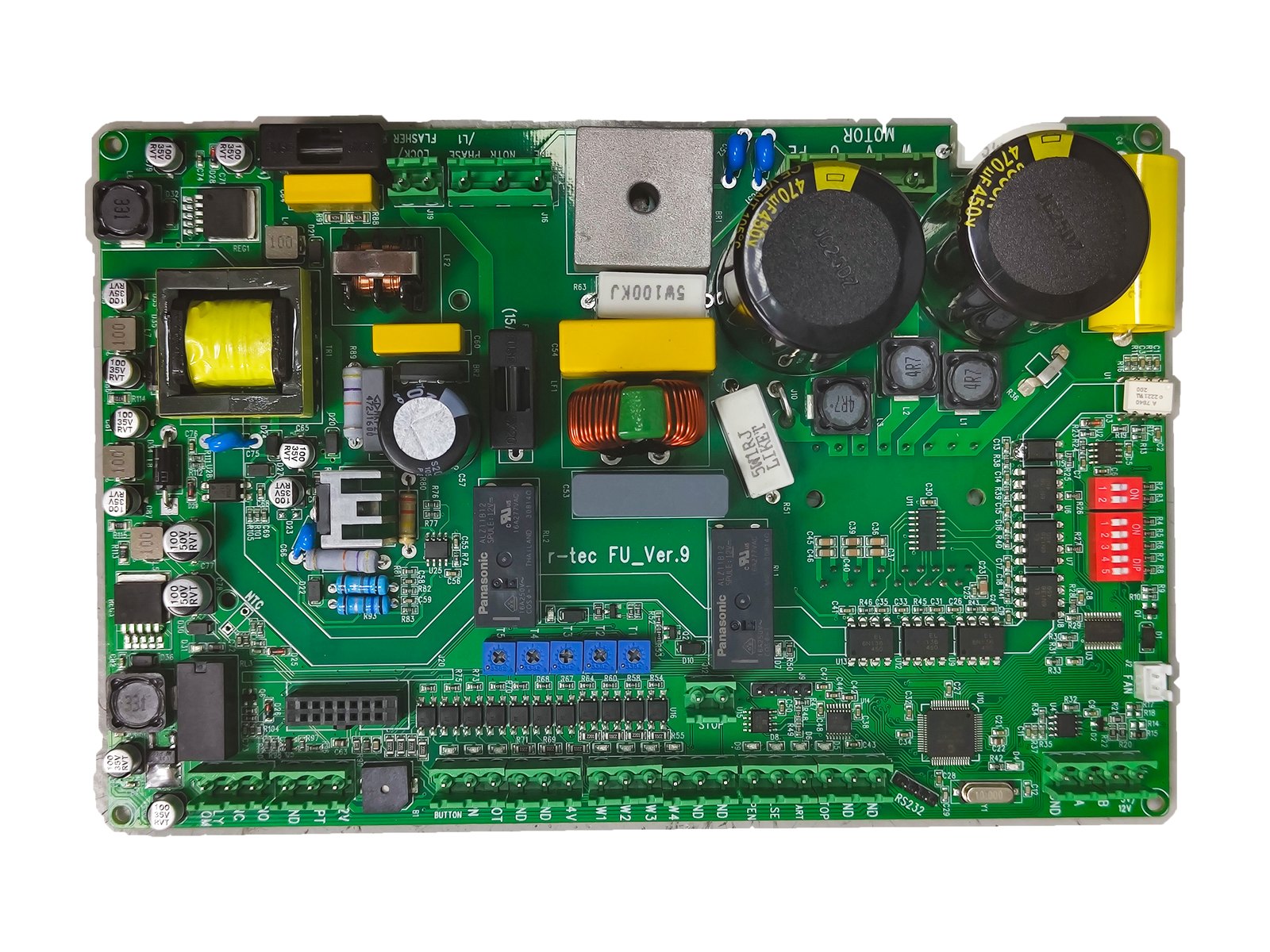
FU is a frequency-inverter control unit with a single-phase 220 VAC input and three-phase motor output. The manual describes soft start and stop, as well as applications involving sliding garden gates and rapid PVC door motors. Check the proposed motor, controller and door combination for the particular project.
Two conflicts in the source
The technical table on PDF page 2 gives the motor output as 3 × 220 VAC, while the prose on the same page says 3 × 230 VAC. The exact output voltage is therefore omitted here; motor matching requires an approved revision.
The newly linked full English FU manual, page 2, also describes 3 × 220 V motor output. The Turkish technical PDF page 2 gives 3 × 220 VAC in its table but 3 × 230 VAC in the prose. These are separate language editions; the 3 × 230 V statement cannot be ignored to claim a settled output value.
The wiring diagram on PDF page 3 labels DIP 5 OFF = flasher, ON = brake board. The control-DIP table on page 4 instead describes the same switch as selecting garden-gate and rapid-PVC motor modes. This PDF cannot establish the correct SW5 function or position. Commissioning must follow a current manufacturer-approved instruction.
Documented controls
| Control switch | Function in the manual |
|---|---|
| SW1 | Automatic close, with the waiting time set by T5. |
| SW2 | Limit teaching for encoder motors. |
| SW3 | Optical sensor activation. |
| SW4 | Reversal of operating and deceleration limits. |
| SW5 | Conflicting descriptions on PDF pages 3 and 4; approved revision required. |
A separate pair of motor-type DIP switches lists 0.75 / 1.1 / 1.5 / 2.2 kW choices. Control SW2 must not be confused with SW2 in that separate motor-power group.
Speed and position connections
T1 adjusts opening high speed, T2 closing high speed, T3 start frequency, T4 slow speed and T5 the automatic-close wait. The wiring diagram labels Sw1–Sw4 as closing limit, closing deceleration, opening deceleration and opening limit. Encoder terminals are 5 V/12 V, B, A and GND; the diagram shows 24 V as a separate terminal.
Receiver and commissioning scope
PDF page 6 describes an optional external socketed RF-433 receiver. Its remote-enrolment counts belong to that receiver option, not the standard FU controller. The PDF gives no fault-code table, one-minute reset procedure or universal installation recipe for every motor. Qualified personnel should confirm wiring, motor compatibility and DIP positions against the approved current instructions for the installation.
Frequently Asked Questions
Below we've compiled the most common questions and answers regarding this product.
-
What if the FU shows a fault?
This technical PDF contains no fault-code table or one-minute reset instruction. For a fault, use the current service instructions for the exact unit and a qualified technician.
-
How are FU speed and DIP settings verified?
The manual identifies the T1–T5 trimpots and SW2 encoder-limit teaching. Its page 3 flasher/brake description of SW5 conflicts with the door-mode description on page 4, so confirm the switch function and position from an approved current manual.
Contact our team for model-specific information or a quote.