


Technical files
Documents
Specifications and installation information can be viewed or downloaded as PDFs from our server.
Technical specifications
2Videos
You can find all of our product and installation videos on our YouTube channel.
Visit Our YouTube ChannelKey technical specifications
The most critical technical parameters of this product.
- Channel count Single channel (Ultra II)
- Operating principle Induction (copper wire frame)
- Supply voltage 12-24 VDC or 24 VAC
- Wire cable 1 × 1 mm² NYY (water-resistant copper)
- Number of turns 5 turns (fixed, stacked)
- Channel dimensions 3 cm width × 5 cm depth
Show all technical specifications (13)
Mechanical
| Feature | Value |
|---|---|
| Typical loop sizes | 100 × 200, 100 × 250, 100 × 300 cm |
| Distance from control unit | Min. 25 cm separate enclosure |
Performance
| Feature | Value |
|---|---|
| Frequency selection | 4 frequencies (Low / Med-Low / Med-High / High) — dip switch 3 + 4 |
Control
| Feature | Value |
|---|---|
| Automatic sensitivity | Enabled / Disabled (dip switch 2) |
| Relay output mode | Sensitivity active or continuous output (dip switch 1) |
| Sensitivity adjustment | 0-9 position (potentiometer) |
| Output contacts | NO + NC + Common (3 terminals) |
Overview
r-tec Ultra II Loop Detector is a single-channel induction sensor that detects vehicle metal mass via a copper wire frame buried underground. It is a critical accessory for KGS (Card Access System) and OGS (Automatic Passage System) integration in barrier automation, industrial door and park automation applications.
How does it work?
The wire frame works as an inductor. When a vehicle comes over the frame, the metal mass changes the inductance; the detector electronics detect this change and close the relay output. The output contact is connected to the barrier/door control board → the door opens.
Operating principle advantage:
- Weather conditions don’t affect — Rain, snow, fog do not disturb detection
- No optical obstacle — No blockage risk compared to photocell
- Long life — Works for many years underground
- Detects all vehicles — Including bicycles, motorcycles, trucks
Wire frame field installation (PDF wiring diagram)
- Cut the channel — In the vehicle passage area, a 3 cm wide, 5 cm deep channel (disc cutting)
- Channel size — 100×200 cm, 100×250 cm or 100×300 cm (based on passage width)
- Wire turns — 5 turns stacked, 1 × 1 mm² NYY (water-resistant) copper wire
- Secure the cable — Wrap with electrical tape every 40 cm
- Braid the ends — Braid the wire ends and connect to Loop1-Loop2 terminal inputs
- Fill — Cover the top with smart filler putty
- Detector position — Keep in a separate enclosure min 25 cm away from the control unit
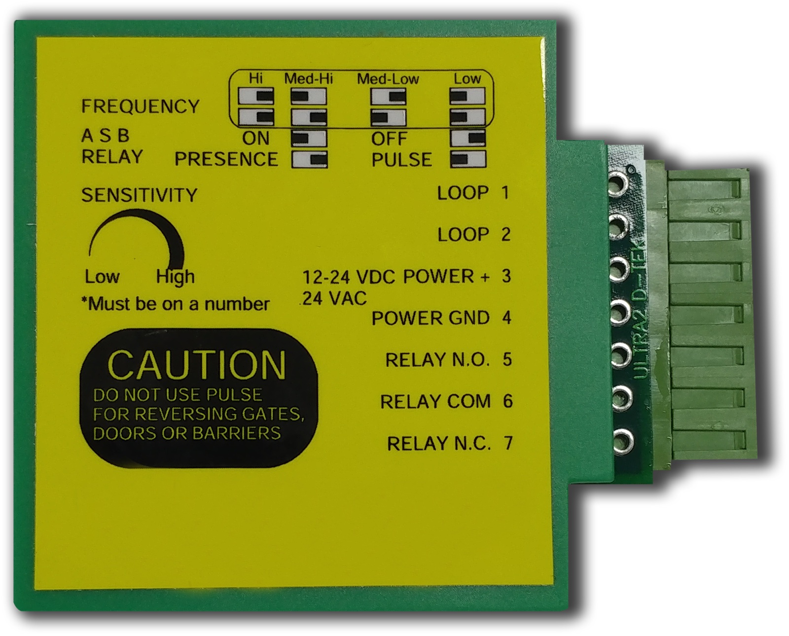
Wiring diagram (PDF — 7 terminals)
| Terminal | Function |
|---|---|
| 1 | Loop wire 1 |
| 2 | Loop wire 2 |
| 3 | 12 VDC – 24 VDC/AC |
| 4 | GND |
| 5 | NO Contact |
| 6 | Common (COM) |
| 7 | NC Contact |
Frequency adjustment (dip switch 3 + 4)
To avoid interference between two nearby loop detectors, run at different frequencies:
| Frequency | Dip Switch 4 | Dip Switch 3 |
|---|---|---|
| Low | ON | ON |
| Medium-Low | OFF | ON |
| Medium-High | ON | OFF |
| High | OFF | OFF |
Automatic sensitivity + relay mode
- Dip Switch 2 — Sensitivity: enabled (ON) or disabled (OFF)
- Dip Switch 1 — Relay output mode: sensitivity active (ON) or continuous output (OFF)
- Sensitivity pot (0-9) — Low → High based on site
KGS / OGS integration
KGS (Card Access) and OGS (Automatic Passage) systems perform two-factor verification with the Loop Detector:
- Card reading + plate recognition → Authorised vehicle verification
- Loop Detector → Vehicle physical presence verification
- → Barrier opens
Without Loop Detector, bot bypass is possible — a fake card signal can open the barrier, but the loop detector verifies the absence of a vehicle and the system blocks.
Target projects
- Shopping mall and plaza car park entries
- Logistics terminal vehicle flow control
- OSB and industrial facility entrance
- Highway toll and special road control
- Closed estate residence vehicle entry
- Hospital + airport emergency entrance
Field discipline
- Loop size selection — 100×200 / 100×250 / 100×300 cm based on passage width
- Number of turns — PDF specifies 5 turns (per loop), with 40 cm tape fixing intervals
- Frequency clash — Two nearby detectors must be on different frequencies (dip switch 3+4)
- Control distance — Keep the detector min 25 cm away from the control unit
- Sensitivity calibration — Potentiometer calibrated with a test vehicle at first commissioning
- Excavation isolation — Wire insulation must not be damaged; if rainwater enters, the detector fails
Contact our team for model-specific information or a quote.